Introduction
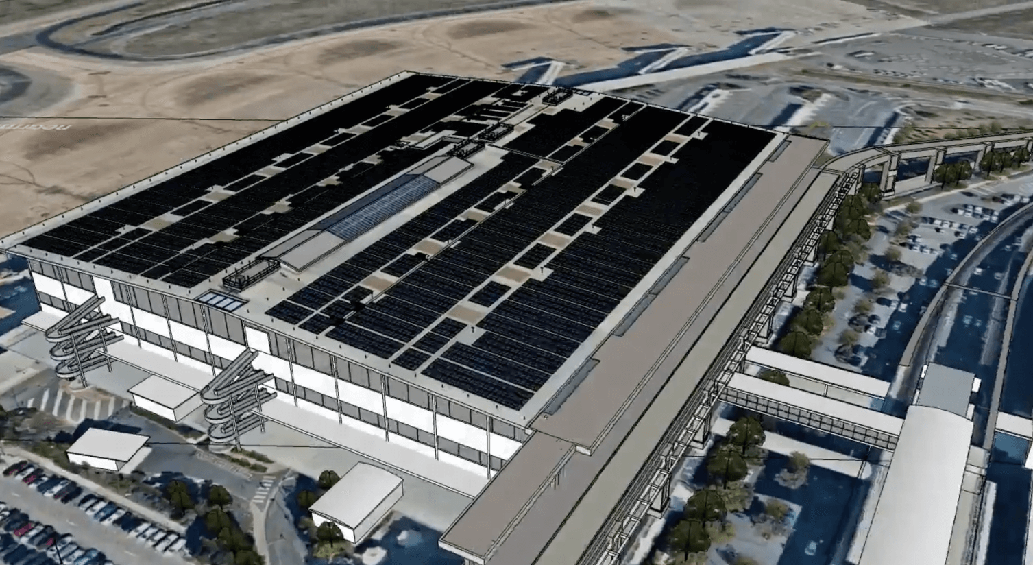
Your commercial solar has just been completed and become operational.
The next step is a comprehensive third party post-installation workmanship audit of your PV system that ensures everything is compliant, free of defects and stands up to rigorous engineering standards. In addition to ensuring the system is safe, conforms with warranty installation requirements and increases the long-term condition, safety and performance of your asset.
These audits are often far more thorough than the mandatory electrical inspection; and audit a number of things not included including a thorough audit of all items of a solar installation; clamping zones, framing fix locations and conformance, compliance with structural certificate, compliance with installation product guidelines, terminal tensions, cable protection and support among others.
Any defects are compiled into a report with photographic evidence alongside recommended solutions. We highly recommend that these be conducted prior to practical completion and prior to final invoicing of your solar installation; and we highly recommend a third-party post installation audit is included as a requirement in project specifications.
Having conducted countless owners' engineer inspections for commercial and solar farms, the Enhar team has noted that certain defects tend to appear more frequently.
This article is a compiled list of common defects and their descriptions and is written as an educational guide to assist installers in better assessing their installation procedures and techniques, thereby circumventing expensive missteps for stakeholders.
Let’s dive in to the top ten common defects:
1. Clamping Zones
All solar panel manufacturers have a zone in which they require their modules/panels to be clamped.
These clamping zones vary by panel manufacturer, and even by module model; and requires conformance to ensure warranty conditions.
Additionally, most manufacturers specify a recommended minimum clamp size, tightening torque and minimum gap between modules.
Installers should check the installation manuals at the start of the job to make sure the framing is installed in a position that allows the clamp zones to comply.
Risk: Voiding of solar module warranty
2. Framing fixing locations
Similarly to the panel clamping zones, the frame manufacturers, in conjunction with the structural engineering report for the roof on which the solar is to be installed, will specify minimum spacing between feet.
Feet will also likely have to be within a certain distance of a purlin for non-penetrative clamps.
These spacings will likely also vary with the location on the roof with tighter spacings typically found closer to the edges and corners of the roof.
Special attention should be paid to the new AS1170.2- Structural Design Wind Actions - Wind Actions which covers wind loads and roof zoning applicable to solar installation; unfortunately standard OEM framing certificates no longer cover most installations by default; and the new standard may increase corner and edge zone locations for most commercial buildings where additional rails or exclusions are reuqired.
Risk: Voiding of framing and/or roof warranty, or in worst case failure of roof cladding.
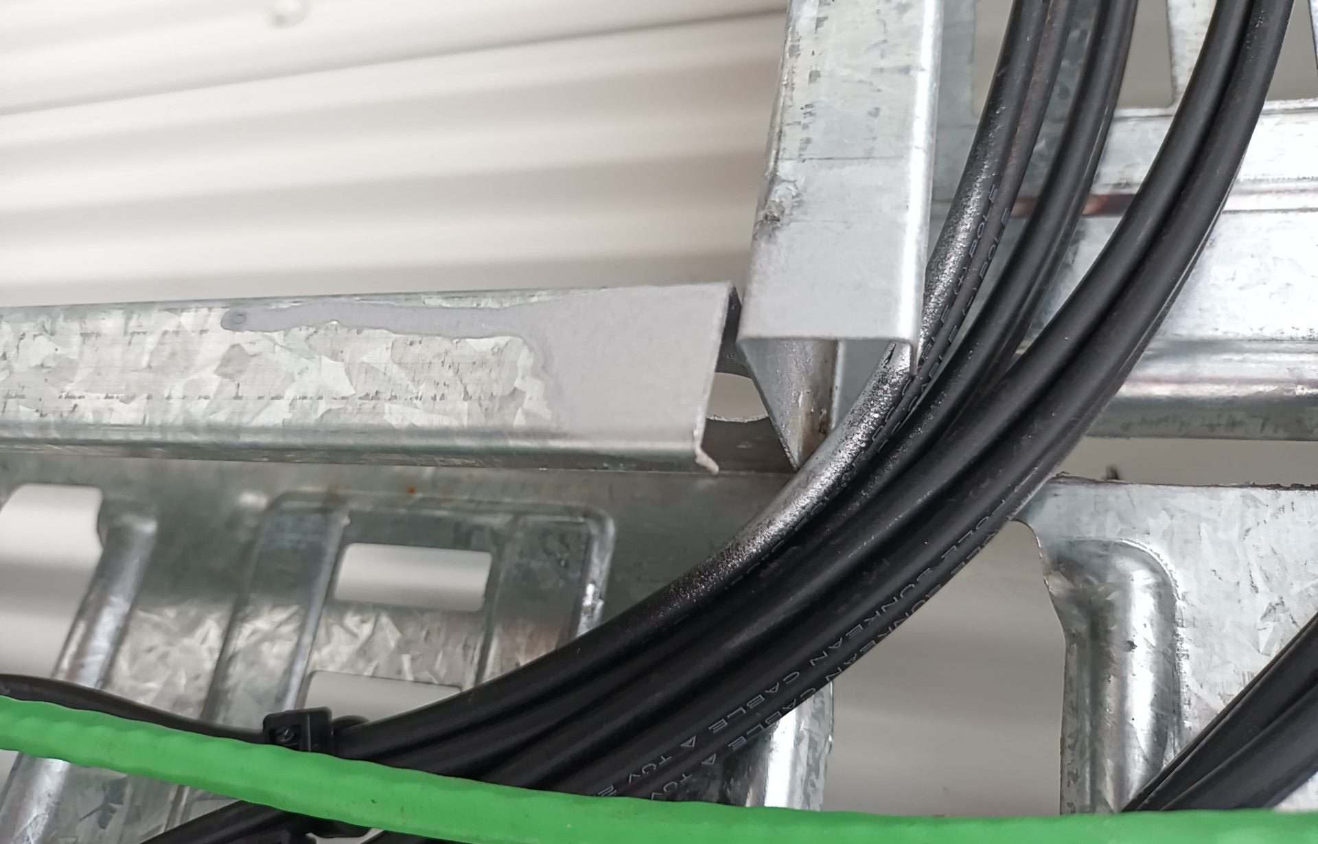
3. Improper use of galvanised materials
The preferred method of containing cables on the roof for most installers is the use of cable-tray. Cable tray is a great way to run cables as it protects the cables mechanically, keeps cables secure and is long lasting – as long as the right type of tray is used.
Unfortunately all galvanising isn’t equal and some trays only have a skin-passed galvanising layer, which is designed to be used indoors, or as a primer for future hot-dip galvanising.
Installers should ensure that where they are installing outdoors, that hot-dip galvanising materials are used suitable for out door usage. Additionally, any cuts that are made into these materials should be appropriately cleaned and sealed with the use of a zinc or galvanising spray.
Risk: Premature degradation (rust/corrosion) of supporting structures.
.jpg)
4. Sharp edges in cable trays
Whilst we’re talking about cables in trays and enclosures, we should mention that attention needs to be paid to sharp edges in cable trays.
If a cable passes by a cut edge some sort of precaution should be taken to ensure that the cable insulation does not get damaged by the sharp edge.
Two good ways of making sure of this are to either fold the edge over on itself so that the edge becomes a “rolled edge”, or by using a rubber edge trim.
Risk: Damage to cables causing system failure or hazardous circumstances.
5. Cable Segregation
Cable segregation refers to the requirement to keep AC, DC and Data cables separated by 50mm, or by use of a suitable barrier. There are multiple standards referring to this which aim to prevent electrical shorts in the event of insulation breakdown, and also to ensure data packets are sent and received without interference.
Risk: Breakdown of insulation may see unintended voltages on some conductors. Potentially causing damage to the system, or presenting as an electrical hazard.
6. Array Earthing Requirements
A recent (2021) change to the solar standards saw a change to the array earthing requirements. Installers should refer to their copy of AS5033:2021 and pay close attention to Table 4.6.
The default earth cable that most installers reach for when earthing the array is 4mm building wire and most of the time this is fine, however this may not always be correct so it’s best to make sure.
Lifting a bunch of panels to replace an earth cable isn’t much fun!
Whilst on the topic of frame earthing, if using Clenergy racking, make sure to earth all rails as they specifically note this requirement in their manual.
Risk: Inappropriate fault return path may result in electrical hazard.
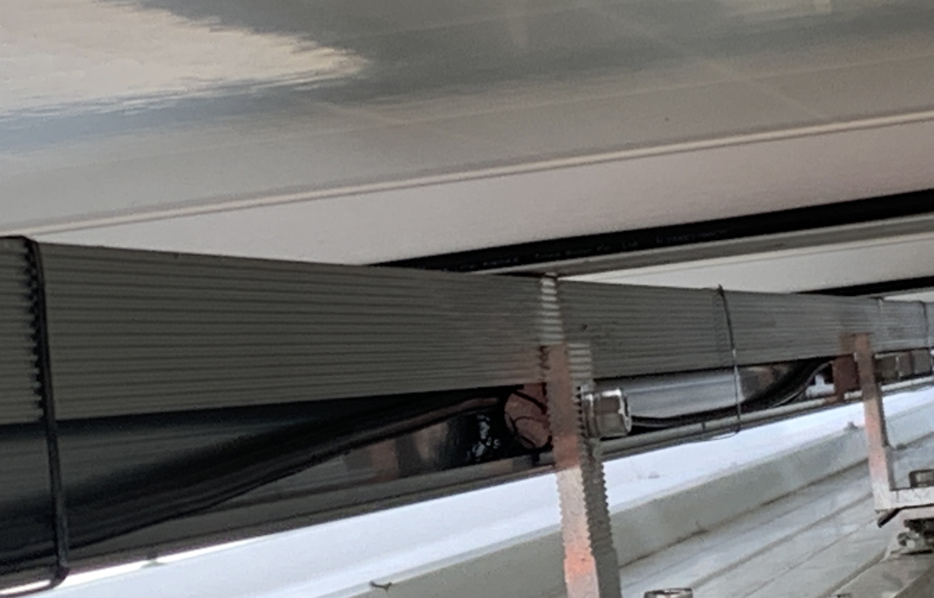
7. Cable Routes
When running DC cables to the modules, many installers will thread the cables through the channel on the rail that is provided to mount the feet. Unfortunately, whilst this may be a neat solution for cable routing, it does potentially create some problems with regards to cable strain and damage.
Cable insulation can be torn or cut whilst being pulled through. Even if a system is tested with an insulation resistance tester at completion of strings being wired, over time the aluminum rails can expand and contract due to thermal cycling, which may create a fault over time; cables should not be run through the rails.
We recommend the use of conduit, cable clips, or stainless steel cable ties when running cables under panels; and of course remember that plastic cables ties don’t last long on a roof and steel table ties are required for the primary use of cable support.
Risk: Electrical hazard or loss of production from the system.
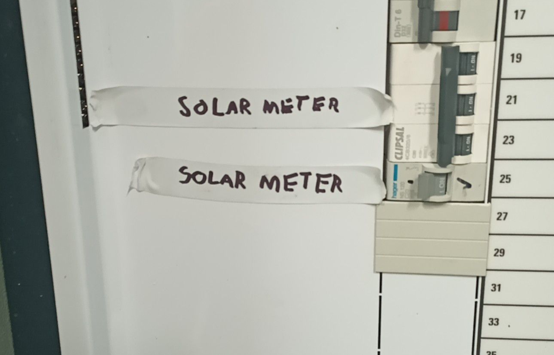
8. Non-Permanent Labels and Markings
When is a permanent marker not permanent? When it’s used to add details to permanent labelling.
Permanent markers fade over time, and can even be rubbed off with a little water in some cases.
If you’re adding details to an engraved label, use a portable engraver to make sure the identifications you are adding will stand the test of time.
Risk: Future maintenance staff may not be able to identify how the system is wired which results in hazardous and costly rectifications that otherwise may have been routine.
9. Unmarked or Incorrect Labelling
Often during an inspection we find isolators and strings that aren’t labelled, or are incorrectly labelled.
It’s important that someone who isn’t familiar with the system can easily identify which string they may be isolating during maintenance or rectification works.
This identification should be consistent on all plans, drawings and labels.
Risk: Future maintenance staff may not be able to identify how the system is wired which results in hazardous and costly rectifications that otherwise may have been routine.
10. Labelling Inconsistencies
Finally, at number ten, we have another labelling inconsistency. Care should be taken by installers to correctly label main switches and main isolators. This can get confusing, but we’ve found the best place to look to make sure you’re correctly labelling these items is AS4777.1:2016. Figures 5 and 6 of this standard provide good information that can clear up most confusion.
Risk: Future maintenance staff may not be able to identify how the system is wired which results in hazardous and costly rectifications that otherwise may have been routine.
Bonus: Terminal Torque
On a vast majority of systems that we have inspected, we find terminals that are not tightened to their required torque. All inverter manufacturers specify how tight the terminals should be, and unfortunately they are often found to be well under the specified value and under-torqued.
Whilst they can be a bit hard to source, an insulated torque screwdriver should be added to every electrician's tool bag to ensure that all their work is tightened appropriately.
Risk: Loose terminations can get hot and result in damage to the system, and in bad cases, cause a fire.
.jpg)
Conclusion
Understanding and addressing common defects is paramount for ensuring both the longevity and efficiency of a solar system and to avoid expensive rectifications to maximise their return on investment in renewable energy.
In this article, Enhar has shared the top ten frequent issues identified in post-installation audits, alongside their potential risks, spanning from voided warranties, premature degradation, system failure, to electrical hazards and fire risks.
The recurring theme throughout these points emphasises the role of diligent preparation, meticulous installation, correct materials usage, and thorough documentation, such as labelling and marking.
It is crucial that installers understand and adhere to the specific requirements set out by manufacturers and regulatory standards, and in order to be certain the installation meets these standards, it’s recommended that a post-installation inspection take place by an owner's engineer.
If you want to be certain that your commercial solar or solar farm installation meets rigorous standards, reach out to the Enhar team and we are happy act as the engineers on your behalf.